Bridge circuit
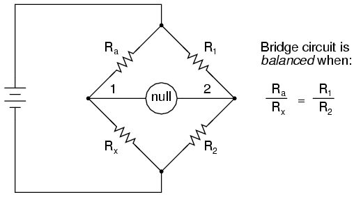
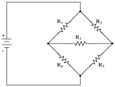
A bridge circuit - also called H-bridge circuit, full-bridge or H-bridge - is an electric circuit, in which in the basic form five two poles are connected together in the form of the capital letter H. The cross-connection is called bridge arm.
- 3.1 Energy technology and power electronics
- 3.2 Measurement Technology
- 3.3 Communications Engineering
Principle
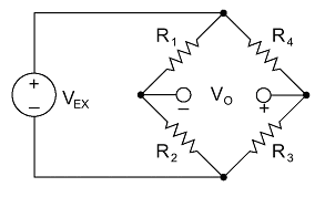
A bridge circuit of resistors can be interpreted as a parallel connection of two voltage divider between the output terminals of the bridge arm. The advantage of the bridge circuit from a single voltage divider is that it can change the voltage and the current in the bridge branch, depending on the setting of the resistance not only in height but also in polarity.
In this case (variable two resistors), half (variable resistor ) is (variable four resistors ) distinguished and full-bridge with bridge circuits between quarters.
The measured object - a resistor or other impedance - is part of the voltage divider on the one hand. At least one other part is made variable so that a field calibration of the current (or voltage difference ) can be performed in the bridge branch, which allows a very precise valuation, since a zero crossing can be determined much more accurately than an extremum. The meter in the bridge connecting branch can usually distinguish between negative and positive values and thus also provides a notice needs to be changed in any direction. The adjustment is made until the instrument as accurately as possible provides a zero indicator. To this end, the instrument with some measuring bridges in its sensitivity is switchable, so you can switch to coarse - fine adjustment of one. The impedance of the DUT is indicated by the setting of the adjustable bridge member (or calculated from the indicated value ).
Only for measuring pure ohmic resistors can operate the measuring bridge with DC voltage. For the measurement of impedances ( coils, capacitors), operation with AC voltage is necessary, which can also be beneficial for ohmic resistors. Not necessary, but helpful in these cases is the display of the phase angle to show the direction of the detuning. See also in AC bridge.
Using, not a zero balance, but the deflection method then can be calculated from the magnitude and phase of the impedance unbalance voltage. Thus, the ( equivalent ) loss resistances of coils or capacitors can be determined without the need to be replicated in the other bridge arm.
Calculation
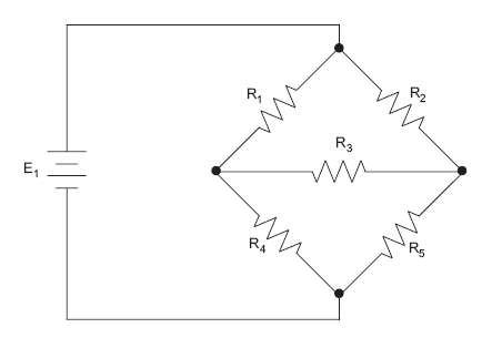
A bridge circuit can be best described through the Kirchhoff's rules. To this end, one first on the node and mesh equations. Optionally one can represent the derived therefrom correlations in a matrix equation. A particular challenge is the computation of the overall circuit resistance, as will be explained later.
Setting up the node and mesh equations
When setting up the node and mesh equations, we go in this example from the assumption that the currents flowing in the direction of the voltage arrow. If this assumption is wrong for a current that is obtained for the amount of the respective current, a negative sign, which does not however change the validity of the equations. From the Kirchoff's rules ultimately results in the following node equations:
Through the mesh typically yields the following equations:
Here, the equations are not completely linearly independent, which is why you can not leave an equation.
In addition, for the individual resistors, the relationship
Or written out:
Herein, the resistance of the resistance of the circuit from the perspective of voltage source dar.
Matrix representation of the node and mesh equations
The matrix representation is a help for large systems of equations and, therefore, especially for large circuits. To determine the matrix representation, one uses the respective product of the resistance and power for the individual voltages. From this we obtain:
The matrix representation is preferred for use in computer algebra systems or in circuit simulators, as for example with the Gauss and Gauss - Jordan algorithm as well as the Cramer 's rule exist efficient solution algorithms. However, in the given example, the Cramer's rule is applicable only to a sub-matrix, since the determinant of the matrix would be left due to the upper four rows is always zero.
Calculate the circuit resistance
The calculation of can be achieved by means of the on the Kirchoff's rules established relationships. A faster variant, the following procedure is:
Alternatively, and with less computational effort can be calculated with the help of a star-delta transformation. For this purpose, rsp. And replaced by their star equivalent. Thus, a simple circuit with two series resistors results in parallel and all connected in series with a fifth resistor.
Balance condition
A bridge circuit is called balanced when no current and thus of a bridge arm in the other flows. If this is the case, the following applies:
It follows the relationship:
Explicit solutions
For those who visit this page because they have to solve specific tasks to the bridge circuit:
The following system of equations ( in matrix notation ) is not redundant, ie, a minimum set of independent statements and is releasable to the rules of matrix inversion.
So do given the resistance values and the source voltage.
Then for the auxiliary variable - this is the value of the determinant of the coefficient matrix left standing -
Hereby
If the bridge is balanced, ie, applies
Is arbitrary. ( The balanced bridge (only one! ) May, therefore, as separated as desired in calculations or shorted viewed in cross section, that is equal to infinity or zero. )
The first of the four series resistors is determined by the other three, because
Applications
The bridge circuit is used, among other things, as a basis for the following circuits:
Power Engineering and Power Electronics
- The bridge rectifier converts AC power to DC power.
- Jumpers ( full bridge, half bridge ) are used in switching power supplies, motor controls and drives.
- Four-quadrant
- Output stages of audio amplifiers are usually designed as a half bridge, but can also serve as full-bridge (BTL, of Engl. Terminated Bridge Load ) may be formed.
Measurement
- The Wheatstone bridge is used to determine medium- ohmic resistors.
- Bridge circuits with strain gauges for force or pressure measurement (see: Wheatstone bridge ).
- Thomson bridge is suitable for measuring small ohmic resistance.
- With the Vienna bridge capacity can be measured with the Maxwell bridge or better the Maxwell - Wien bridge inductors.
- The Wien- Robinson bridge is used for frequency measurement.
- Schering bridge to determine the capacitance and the dissipation factor of the capacitors, mainly used in high-voltage engineering.
Communications Engineering
- Ring modulators are similar in circuit construction bridge rectifiers, but serve to modulate signals.
- Measuring bridge


