Bending moment
As a bending moment, a moment is called, which loads a slim body, mount, shaft or a beam to bending by a force acting through a point or distributed load at a given distance from a warehouse in one plane. The bending moment is expressed in the SI unit Nm. It can be calculated with the formula. Therefore, it is a torque.
Bending moment in the beam theory
The beam theory describes the behavior of a beam under load, especially its deflection due to the occurrence train and pressure loads. Thus, the beam theory is a branch of statics and strength of the theory of elasticity, as well as a basic component of the technical mechanics. Often, one also speaks of the flexural theory of the beam. Required for strength considerations, the maximum bending stress in the beam cross section can be determined from the given bending moment and the moment of resistance of the cross-sectional area.
Bending moment in beams
, A bending moment occurs even when a carrier with two or more bearings.
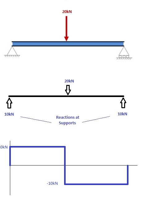
For a loaded beam with a force F on two supports is in the introduction of force in the center of (l / 2 ) the amount of the bending moment is greatest.
There is a maximum. The bending moment in the beam cross-section at the two ends of the support x = 0 and x = L are each equal to zero.
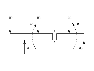
To calculate the moments of the inner member is cut to the site of interest mentally and are considered those moments that act on a portion with respect to the interface. The bending moment at a location so that the sum of the torques which are caused by forces on one side of the interface.
You can perform this procedure on any of the two sections, as opposed to out of equilibrium reasons for both sides yield the same values.
Bending moment at a stored beam at its ends
In supported at its ends beams with central concentrated load ( drawing on the left ) is subject to the left portion of a clockwise torque ( in the technical mechanics for short moment ) that on the left bearing is writable using the tracking force FL = F / 2. The torque increases from zero at the supports linear up to the maximum value in the middle. Right of the center comes from the stressful force F added a value from zero up to the same maximum value at the right abutment rises linearly, left turning moment, so that the moments sum of the maximum value in the center decreases to zero linearly at the right end.
In the middle of the beam ( ), the bending moment is at a maximum and has the value:
Bending moment and bending line
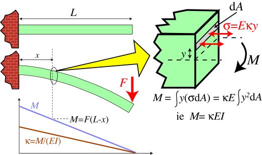
The shape of or the bending line of a bent elastic member ( beam ) having a constant cross section, the bending moment: is subjected to ( index y deflection about the y -axis) can be described by the following approximate formula:
The elastic modulus is a material property that is the axial moment of area ( a purely geometric quantity ) of the beam cross-section, of the device on its behavior in bending about the axis.
The curvature is proportional to the bending moment.
In supported at its ends beams with central concentrated load ( drawing above ) are both in the middle of the greatest.
Bending moment and bending stress
Caused by the bending moment bending stress in a cross section of a beam may be determined as follows:
The bending stress is the same as the curvature of the slender member is proportional to the bending moment. In the example, it is therefore also at midspan greatest.
The amount of bending stress plays a role investigate is whether the bar can withstand the stress, not permanently deformed or even broken. She is in the beam cross section is proportional to the distance from the neutral axis (usually through the centroid of the cross section continuously ). At the maximum, that is, in the upper outer fiber ( inside of the curve ) is the largest compressive stress in the bottom fiber edge ( outside of the curve ) creates the largest train voltage.
Because at constant beam cross -sectional area moment of inertia is constant, can be quotient with the distance of the extreme fiber to the constant resistance moment
Summarize. So that the formula applies for the faults in the outer fiber bending stress:
In supported at its ends beams with central concentrated load ( drawing above ) created with the values and The following limit equation against bending failure:


