Water wheel
A waterwheel, often called water wheel is a wheel that is rotated by water power in rotation. Here, the potential and kinetic energy of the water is used to drive water mills of all kinds, generators of small hydropower plants, or water pumping stations.
- 3.4.1 Performance and Efficiency
- 3.4.2 As a hydraulic structure engineered tiefschlächtiges waterwheel
- 3.4.3 Floating tiefschlächtiges waterwheel - Schiffmühle
Importance
In the industrialized regions of water wheels today have little or no economic importance. Most are in the many converted to museums mills, some drive to smaller generators and are used to generate electricity. Partial run water wheels for decorative purposes excluding energy use. In the castle Nymphenburg in Munich water wheels but for over 200 years now, its still the pumping stations for the two fountains in front of the castle. An important difference between water wheels and turbines: water wheels can run in efficiency without control and with strongly fluctuating water levels without significant degradation.
In addition to pure water mills were and are mills that receive their driving force of water and wind at the same time. One of the few still fully intact today such mills is the Hüvener mill in northern Emsland.
Most water wheels are in the developing countries of Africa and Asia as indispensable tools especially the agriculture. The world's available power potential of water wheels should be in the range of several terawatts according to reliable estimates. Typically, a water wheel delivers a driving power in one-to two -digit kilowatt range. It represents a contribution to the sustainable use of water power, as it due to its low power and decentralized arrangement requires only a small impact on nature.
History
The invention of the water wheel by Greek engineers in the 4 / 3 Century BC marked a milestone in the development of technology, since mechanical energy could be harnessed through the use of hydropower. Served water wheels for irrigation in agriculture, as a bucket for lifting water to start. Such bucket wheels are widely used since before the Christian era to the Hellenistic states and the Roman Empire, and later in India and China.
Already in Roman times, water wheels were used to power grinding mills. The Roman architect Vitruvius and engineering describes in his " architectura " from the 1st century BC, both the principle of Wasserschöpfrads and that of the mill detail. The earliest evidence of a water mill in Germany achieved the archaeologists by the excavation of a mill from the time of Christ's birth at the Inde (see Inde (river) story). Finds in the Alemannic settlement agent Mayrhofen in Lauchheim dating from the 6th century. Already in the 9th century there were many mills in central France. Since the 12th century water mills were common in Central Europe. Later, the use of oil mills, fulling mills, saw mills, hammer mills and grinding mills was added. The advent of industrialization was the waterwheel for driving machinery; via the first transmissions. Even in the mountain nature they were used for material transport and for dehydration. So by the plague of 1348 standstill in mining was recorded on lead, copper and silver again in the Upper Harz mining at the beginning of the 16th century. In 1868 Alfred Dumreicher published a detailed description of the Upper Harz Water power system. He is one in 190 water wheels in size from 6 feet ( = 1.73 m) to 40 feet ( = 11.52 m) in diameter. In addition there are three - for that time very modern - water column machines (turbines ) are added. 18 water wheels have a diameter of more than 10 meters and 10 water wheels with 11 meters in diameter and more. Dumreicher quantifies the services provided in this hydropower system performance to 1870 horse-power net. It should be noted that here the water power for the special requirements in the ore - mining was used. One of the main tasks was to promote the ore from the underlying underground mining tunnels on heights of sometimes more than 500 meters to light. A filled with ore conveyor cage at that time had a weight of 300-350 kg. Other tasks were to transport the miners using the driving skills and the lifting of the infiltrated water in the pits.
Another example are the carrots in village on the Regnitz remaining nine historic waterwheels that are already in use for the beginning of the 15th century. One of the largest historic waterwheels Germany is 9.6 m in diameter, which was built from 1745 to 1748 "Big Wheel" in Schwalheim in Bad Nauheim. It drove to the mechanical pump of an early industrial salt production site. The largest water wheel at all is on the Isle of Man. The "Great Laxey Wheel" has about 22 m in diameter and served the dewatering of a mine.
An adequate water supply was an important point in the site evaluation of a number of factories, in contrast to other location criteria at the present time. A key point in order to operate a water wheel, were the water rights. So you can still find property rights of old industrial plants in the headwaters of rivers or larger streams, which are no longer used by the owners. The voltages applied to improve and ensure the mill power mill damming are often available at little waters as mill ponds. On larger bodies of water they had far-reaching effects and were therefore in the Middle Ages a political issue.
Towards the end of the 19th century made it the emerging water turbines possible to use much larger amounts of water and higher gradient. The introduction of electricity, the energy did not have to be mechanically transmitted locally, but could be converted into electricity. It originated hydropower plants, which could produce more cost-effective due to their size and the small power plants with water wheel gradually displaced. Attempts to replace the comparatively small water wheels through turbines failed in many cases, since both drives have completely different properties.
Types of water wheels
Water wheels are classified by type of water supply. Depending on the gradient and the height difference between the inlet and outlet various water wheels are used.
Regardless, a distinction between cells and paddle.
- Cells wheels consist of laterally and downwardly closed containers ( cells ), the maximum hold the water a half turn. This design is also referred to as earthing or anvil wheel. A special form is the Pansterrad is that constructed according to the same principle but is much greater and wider, and therefore suitable for use in rivers.
- Paddle wheels have no cells, but only radially arranged plates or boards ( blades ), which are open to all sides. To keep the water in the buckets, most paddle wheels running in a Kropfgerinne. To achieve high efficiency, the Kropfgerinne needs as closely as possible to the blade rest ( see fig " mittelschlächtiges waterwheel "). This design is also referred to as Strauber or Stelzenrad.
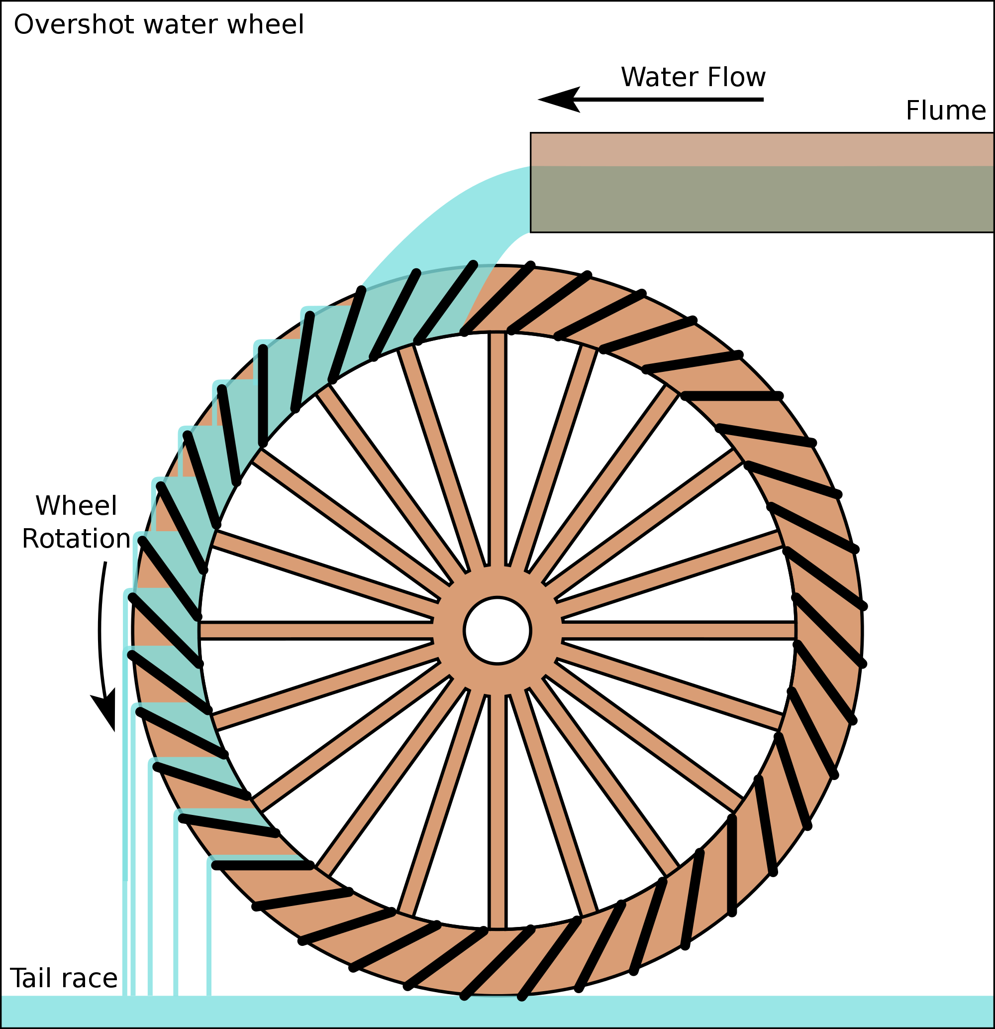
The images " overshot water " and " water wheel mittelschlächtiges " show a feeder, the figure " undershot waterwheel " a paddle wheel.
Overshot water
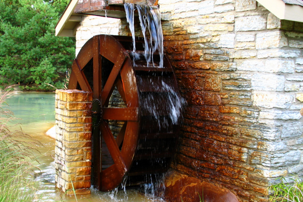
When the overshot water wheel, the water (so-called Flume or Fluder ) or a pipe passes through a groove about the Radscheitel the watertight cells of the wheel. It is therefore also called a feeder. The wheel is offset by the weight of the absorbed water and its kinetic energy ( surcharge water) in motion. The falling height is typically between three and ten meters. Overshot water wheels have been known since the 13th century.
In contrast to the water turbine, a overshot water wheel does not need a rake to filter out floating debris, and the efficiency is less dependent on fluctuations in the amount of water. The application area is located on slopes of 2.5 m to 10 m and water flow rates up to 2 m³ / s (typically gradient 3-6 m and water volumes of 0.1 to 0.5 m³ / s). For Mills, the typical Wasserradleistungen 2-10 kW. Overshot water wheels are operated at peripheral speeds of about 1.5 m / s.
The water is at a small weir, some 100 m above the water wheel diverted from the parent stream and fed into an artificial channel with little slope to the wheel. This channel is often referred to as Obergraben, Mühlbach or upper mill race. The weir serves to regulate the amount of water flowing. The last part of the channel in front of the wheel is called the channel. It often consists of wooden boards or metal. On flume is a free floodlights, also called blank shot, attached, which the water passes over at standstill of the water wheel at the wheel. Another type of investment is that the upper trench is extended to a storage pond. The waterwheel is close behind the pond dam. The flow of water to the wheel is controlled in this type of investment over a Radschütz, which is located at the end of the channel.
Under optimal conditions (especially with blades made of sheet steel ) can be realized efficiencies of over 80 % for the overshot water wheel. However, a water wheel in winter is confronted with icing problems. Enteisungsarbeit the waterwheel is exhausting and dangerous. Therefore, many water wheels were built around a more wheelhouse. The wheel housing not only protects against ice, but also prevents drying at standstill, resulting in an irregular path of the wheel with wooden components. Turbines do not have these problems.
With power: Watts, Efficiency: density of water: in kg / m³, flow rate in m³ / s, acceleration of gravity: in m / s ² and the height of fall, or the wheel diameter in m.
Kehrrad
A special design is the Kehrrad. It is only applied overshot and has two oppositely disposed blade rings, so that it can change its direction of rotation, depending on the actuation. Sweeping wheels found in mining use to drive with hydropower funding. By reversing the direction of the bins or baskets could be raised and lowered. In general, there was a cable drum or a chain basket on the shaft of the wheel. Was indispensable addition, a braking device to slow the Kehrrad can ( brake wheel ). The oldest known representation of a sweeping wheel comes from Georgius Agricola in the year 1556.
Mittelschlächtiges and rückschlächtiges waterwheel
Mittelschlächtige water wheels are about applied at hub height ( " hit the water " ) and use flow and weight of water, so shock and pressure equally. They can be built as a feeder or as a paddle wheel. Mittelschlächtige cells wheels are also called rückschlächtig, they are built like overshot wheels, but rotate in the opposite direction. The transition to the undershot wheels is fluid, also Zuppinger wheels ( See: undershot water wheel ) can be applied almost at hub height.
Some mittelschlächtige wheels have a sliding gate ( 'a' in the schema diagram). This is a generally adjustable guide device, which divides the water into a plurality of partial beams (usually three ), and supplies the wheel a certain direction.
Modern mittelschlächtige water wheels can reach efficiencies of up to 85%, which they approach brings close to the efficiency of conventional turbines with appropriate design of the inlet and outlet as well as chambers and blade shape.
Undershot waterwheel
In undershot water wheels, the water flows under the wheel by a goiter. The goiter ( ' K' in the schema sketch to mittelschlächtigen waterwheel ) is a guide which is adapted to the wheel. It prevents water from below and to the side of the blades flows without driving it. Due to the rather simple design undershot waterwheels are the oldest form of water wheels.
The power transmission takes place via blades. In its simplest form, the blades are made of a wooden board, better efficiencies are achieved, however, with specially curved plate blades.
The application area is located on slopes of 0.25 to 2 m and water volumes in excess of 0.3 m³ / s, or 50 liters per second. This results in a performance in one-to two -digit kW range. Under optimal conditions, especially when the gap between the bolster and the wheel is small, efficiencies of over 70 % can be achieved. Undershot water wheels are operated at peripheral speeds of 1.6-2.2 m / s, this size is an empirical value. Due to the low gradient, the water wheel is usually completed at the weir.
From the 19th century, the Zuppinger wheel, which achieves higher efficiency by involute blades comes. This design was common ( textile industry, chemical industry, steel industry ) before the introduction of steam engines in the industry in the 19th century. It was possible to achieve remarkable performance by some 10 kW by wide wheels made of iron. With speeds of the water wheel slowly walking machines were such as tamping works or tail hammers ( = hammer mill ) are driven directly. Most machines require multi-stage gear drive (so-called counter ) to provide the required speeds. This has favored the use of turbines against the water wheel.
Tiefschlächtiges waterwheel
A tiefschlächtiges waterwheel resembles a unterschlächtigem, but at that the water wheel is immersed in a ( nearly ) flat river and is driven solely by its flow rate. Compared to the undershot waterwheel is here only the natural flow rate of the water body of concern, an increase in the available energy by an artificial slope in the water ( along the water wheel or by a barrage before selbigem ) does not take place.
Performance and efficiency
The service offering of the body of water from its kinetic energy by the flow rate, based on the water wheel influenced by cross-sectional area A, can be calculated as follows:
The performance of a tiefschlächtigen water wheel can be calculated as follows:
The flow of water ( the water in kg / m³ density) exerts a force F ( in Newtons) of the blades of the cross-sectional area A ( in m ) that can be calculated from the dynamic pressure of the flow to the blade:
The drag coefficient is a dimensionless number and can be derived from the corresponding tables. A hollow hemispherical shell which is to flow to the hollow side, has the coefficient ~ 1.35. It should however be noted that, while having a water wheel without a dynamic adjustment of the tilt angle to a perpendicular approach flow ( exzentergesteuerte vanes ) at immersion and emersion flatter angle. The effective average drag coefficient is thus smaller than the read in the usual tables. Exzentergesteuerte vanes thus represent a possible improvement, but are maintenance intensive and cause additional loss to drive the eccentric control, so that they are not translated.
The effective speed for the dynamic pressure is calculated from the flow rate of the river, reduced by the surface speed of the water wheel:
The power of the water wheel P ( in watts) is calculated from
- The product of the force at the surface speed of the water wheel
- The product of the force with the angular velocity of the water wheel and the radius of the water wheel r:
Solving this system of equations by the force F, the dynamic speed and the surface speed of the water wheel are eliminated, we obtain the equation for the power of the water wheel:
The performance is optimal at:
The optimum surface speed is thus only 1/3 of the flow velocity of the river, which is why a modern water wheel should have a speed control to operate it with the optimal speed can. Whether the measurement of the flow velocity of the flow is required by ultrasonic Doppler probe depends on whether the flow rate, depending on the water level fluctuates greatly.
The maximum possible benefit may be calculated as follows:
So Tiefschlächtige water wheels need a high dynamic Anströmdruck by the river and generate a low speed. This has the following effect on the efficiency of:
The efficiency of a tiefschlächtigen water wheel is the ratio of the power of the water wheel and the power supply of the river, if the similarity measure is introduced:
This relationship is illustrated in the following graphic:
- Efficiency of water wheels tiefschlächtigen
Although the efficiency appears to be relatively small in relation to the through an underwater propeller (underwater windmill ) achievable efficiency of ~ 60 % according to the law of Betz ( this is applicable for an underwater propeller, as Betz of a non- compressible medium ran out ).
This is due to the fact that a tiefschlächtiges waterwheel is a simple machine that converts a flow resistance, and thus a friction work. Machines such as propellers or windmills, however, convert the pressure difference of being flocked wings in a maximum torque times speed by. By a clever choice of the profile so much more efficient machines can be constructed. In scenes guided medium-or undershot waterwheels as a variety of displacement machines ( the cell wall as a kind of piston ) are considered and work through the restraint of the water more effective, but are very susceptible to friction losses eingeschlepptem flotsam and are therefore maintenance-intensive. Furthermore flotsam must be disposed of as waste, can not therefore be easily incorporated into the water again below, which causes considerable costs.
Nevertheless, a tiefschlächtiges waterwheel may be a suitable generator to generate electricity from the kinetic energy of rivers, as this just
- Relatively insensitive to the influence of flotsam and
- Consequently incur low maintenance costs which may affect the efficiency of other river plants considerably.
The energy supply from the river so you need not be as high as possible, but are used in the most cost-effective. For a tiefschlächtiges waterwheel is well suited.
As a hydraulic structure engineered tiefschlächtiges waterwheel
The tiefschlächtige water wheel comes from the natural gradient of the water. Unlike undershot waterwheel, there is no setting that turns this into a kind of piston engine. The wheel is frictionally driven solely by the flow resistance of the blade boards ( derivation of the equation of motion see above). The efficiency tiefschlächtigen water wheels is maximum when the circumferential speed of the wheel 1 /3 of the water velocity corresponds.
The principle is especially useful for water bucket wheels used because it is resistant to degradation by flotsam and therefore robust, which is the main advantage in this case, the economy improved significantly (must -deposited from the water floating debris are eliminated costly in Germany as waste ).
It is also closely related to the propulsion of paddle steamers as a quasi right -going process and became displaced by the propeller, which has a much higher efficiency.
Floating tiefschlächtiges waterwheel - Schiffmühle
When the ship ( s ) mills, both spellings are common, this design principle will also apply. Here is the ship is moored in the river; the waterwheel drives the mill on the ship. The boat mill has the advantage that it floats with the water level or drops, thus always the same amount of water is available.
Horizontal mills
Horizontal mills, regionally also called stock or Flodermühle are indicated by a horizontal waterwheel on a vertical shaft. The wheel drives the millstone without gears. It will only be used kinetic energy; the mill therefore requires a river with a steep gradient. Because of their simple and robust design and their suitability for small amounts of water horizontal mills were particularly widespread in arid and mountainous regions of the Mediterranean early; but they are also found among others in Northern Europe and in the Alps.
Special shapes
- The Turas- water wheel is an overshot, one side -mounted water wheel. It is one-sided flange-mounted in a prefabricated frame construction, which is equipped with the gear and Asynchrongeneratoreinheit and stored through the transmission. With this construction, Wasserradwelle omitted.
- The gravity water wheel is a waterwheel mittelschlächtiges, in which the maximum energy the inlet and outlet losses were minimized. Base are the design guidelines for Zuppinger water wheels. The shape of the blades is not for maximum performance, but maximum years of work ( years of work in this case means the average amount of energy produced in a year ) towards optimized. The Gravity waterwheel therefore corresponds more to the needs of today's Wasserradnutzung for energy production.
- The segment Wreath waterwheel is a ventilated water wheel in a modular design.
- The cross-flow turbine is a further development of the water wheel essentially dar.
At Le Locle in the Swiss canton of Neuchâtel (NE ) are Europe's only underground mills, the cave mills of Le Locle. In a multi-storey cave water wheels were installed to power a grain mill and threshing and lumber mills in the 16th century into a waterfall.
Combination of existing mills with other renewable forms of energy
Existing Wasserradanlagen can be combined through the use of generators with other energy generators such as photovoltaics, small wind turbines and cogeneration plants. A charge controller with power management system provides for the regulation and control of energy production and distribution.


